VICTOR ESTRUCH-OYARSABAL

DRAWBOT

2026ECE · Closed-loop systems 9 weeksTeam of three 1 penand a lot of PID tuning

A two-wheeled robot that holds a pen and draws with engineering.

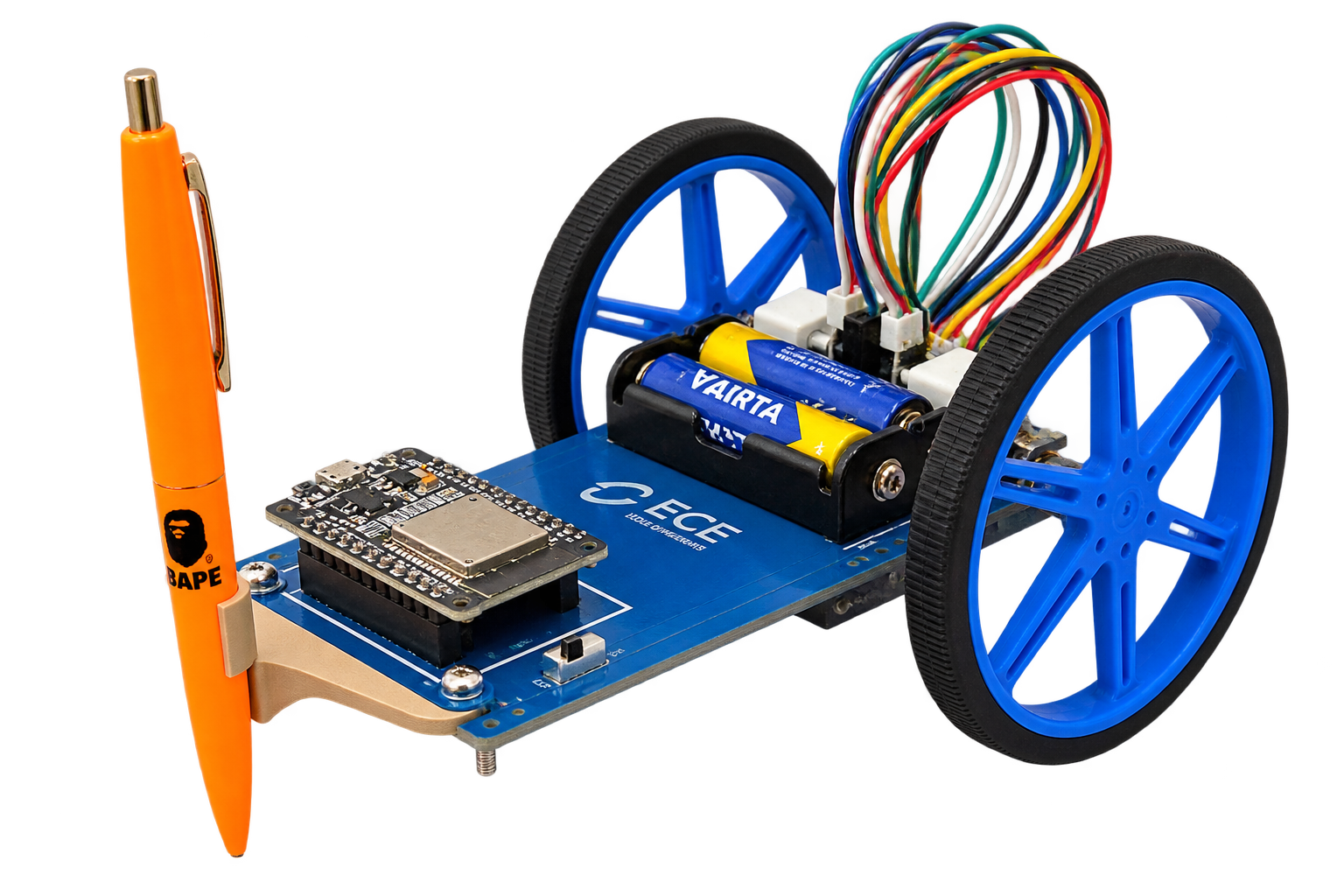
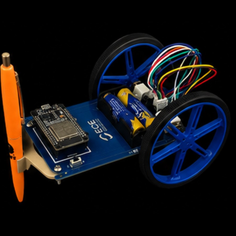
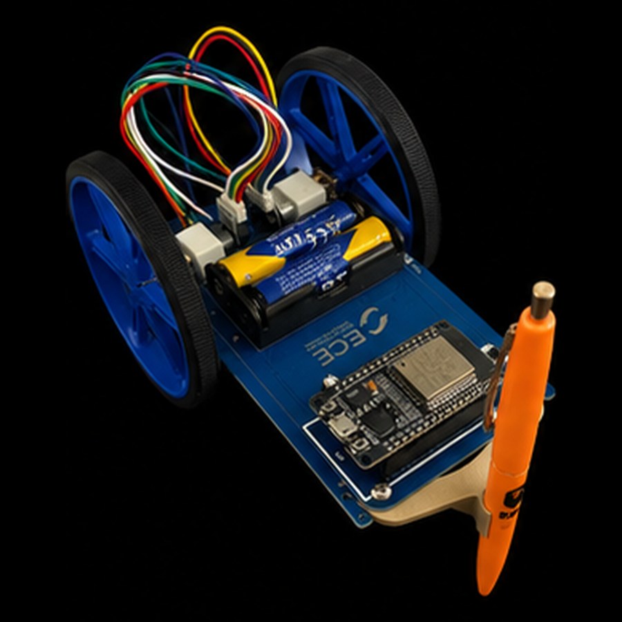
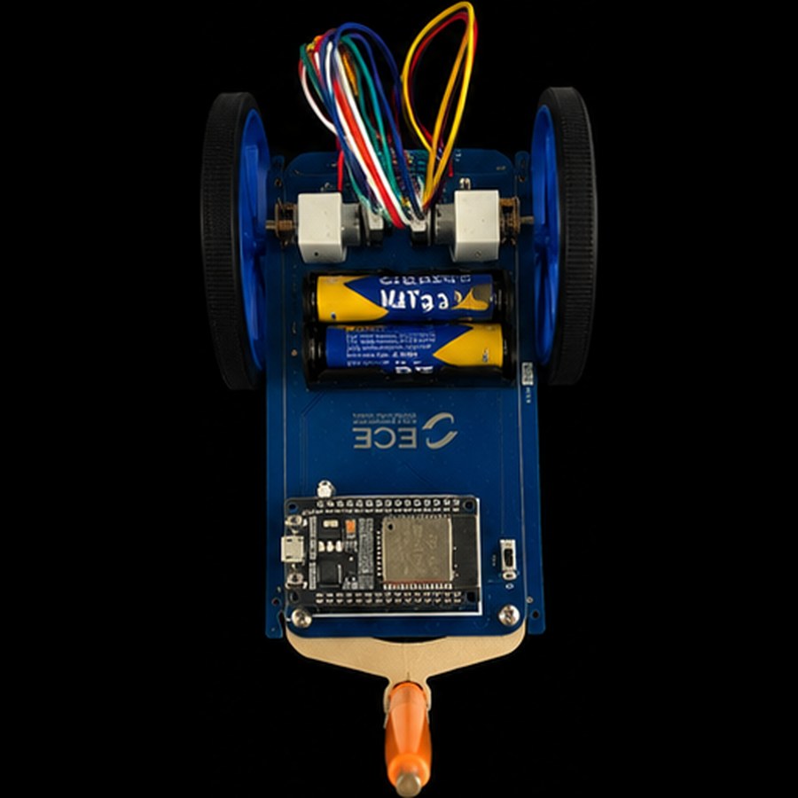
Second-year engineering project at ECE Lyon, built on the school's Gyrobot platform: a bare PCB, two small motors and a felt pen, turned into a wireless robot that draws precise geometric figures: a staircase, a circle of any radius, and a compass rose that finds magnetic North on its own.

Sequences drawn3
Distance tolerance± 1 cm
Angle tolerance± 5°
BrainESP32

Three drawings,
zero excuses.

Sent from a computer, drawn on its own.

Sequence 01

The staircase

20 cm forward · 90° left · 10 cm · 90° right · 40 cm

80% validated

Two motors never spin at exactly the same speed, so an uncorrected robot draws a curve, not a line. Each wheel is read by its encoder and a PID corrector rebalances the motors in real time. The straight lines came out clean; the 90° turns were the fight: wheel slip made the robot overshoot, so we switched to micro-movements with intermediate corrections. The staircase is clearly recognizable, one last angle slightly wider than 90°.

  • Encoders
  • PID
  • Straight lines
  • Rotations
Sequence 02

The circle

Radius set from the computer · closed within 5 mm

Validated 13–20 cm

A circle is one continuous movement where the outer wheel travels farther than the inner one, in a perfectly held ratio. Send a radius from the computer and the robot computes a new pair of wheel targets. With KP = 2.5, KI = 0, KD = 0.5, circles closed within millimetres from 13 to 20 cm. Below 13 cm physics wins: the inner wheel turns so slowly that torque and pen friction stall it, and the circle ovalizes.

  • Differential drive
  • PID tuning
  • Parametric radius
  • Teleplot
Sequence 03

The compass rose

Find magnetic North from any starting angle · ±10°

North found

The first two sequences rely on relative movement; this one needs an absolute direction. The magnetometer reads the Earth's field, the heading is computed from its components, and a rotation loop aligns the robot to North from any start angle. The catch: a magnetometer hears everything magnetic, including the robot's own motors. We moved the test zone, slowed the final approach and softened the gains until the heading settled inside ±10°, verified against a smartphone compass.

  • Magnetometer
  • Absolute heading
  • I²C
  • Rotation loop

Small robot,
real electronics.

Every net redrawn, every polarity justified.

DrawBot is built on the Gyrobot, a PCB designed by ECE's electronics department. My main focus as team lead was reverse-engineering the whole board in KiCAD, redrawing its six functional blocks, down to why capacitor C18's negative leg faces the board centre.

  • NodeMCU ESP32240 MHz · Wi-Fi & Bluetooth · the brain
  • 2 × N20 motors100 RPM · Hall-effect encoders
  • DRV8837H-bridge drivers · one per wheel
  • LSM6DS3Inertial unit (IMU) · I²C
  • LIS3MDLMagnetometer · finds North · I²C
  • 4 × AA cellsOnboard power (VBAT)
  • 90 mm wheelsSilicone tyres + felt-pen holder
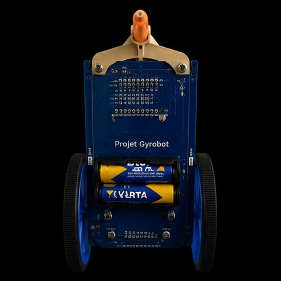
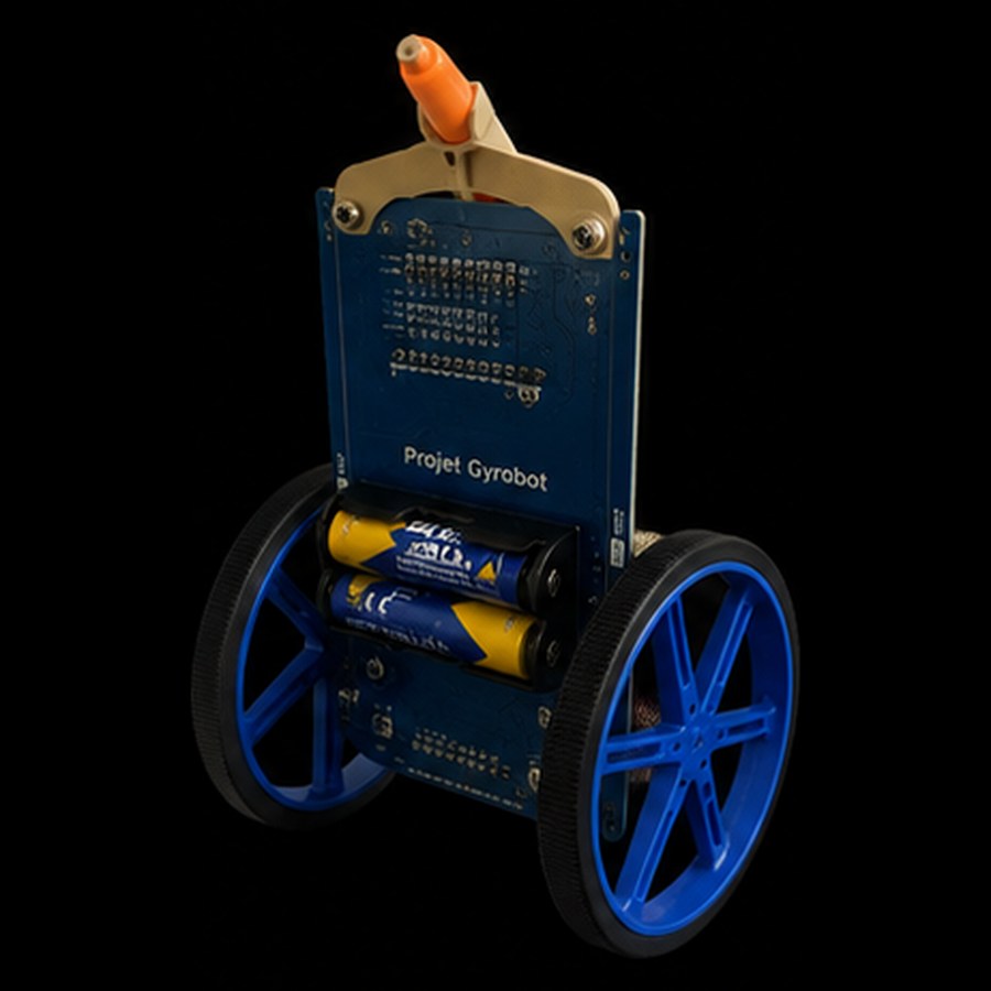
Le DrawBot assemblé sur la plateforme Gyrobot
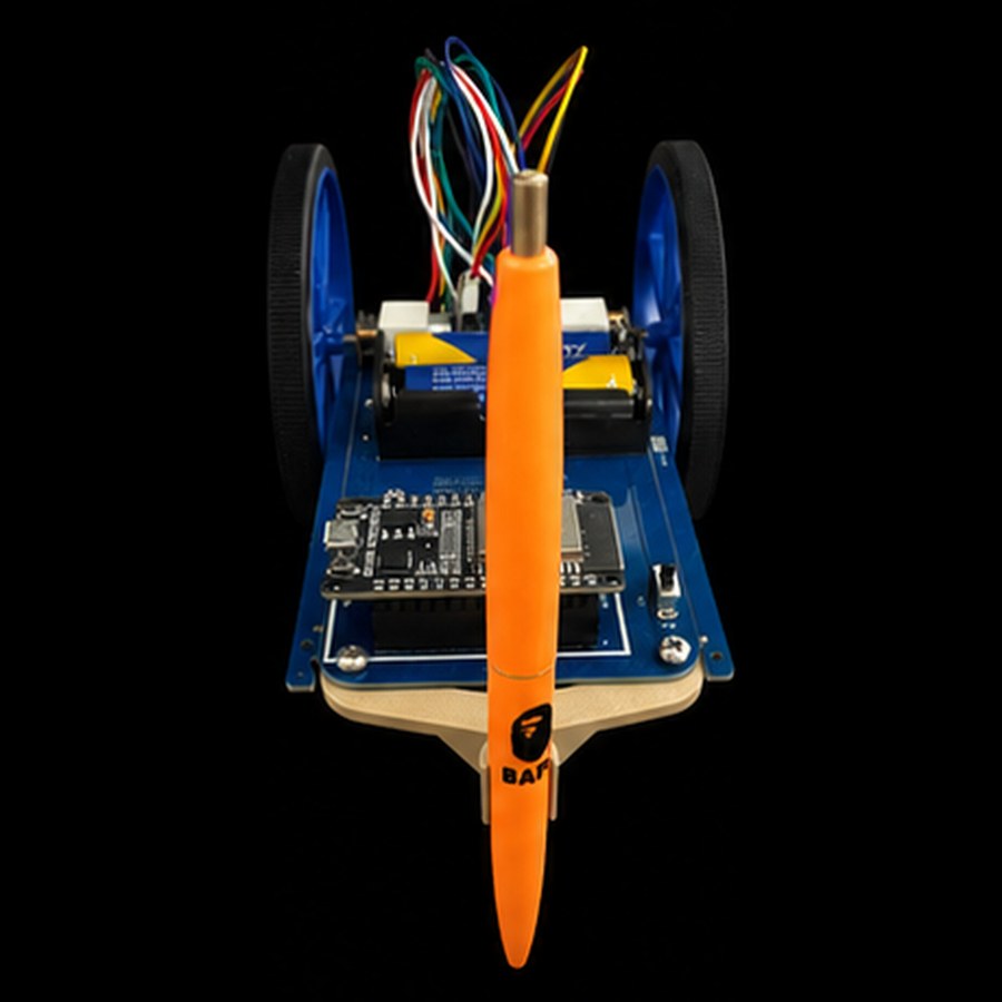
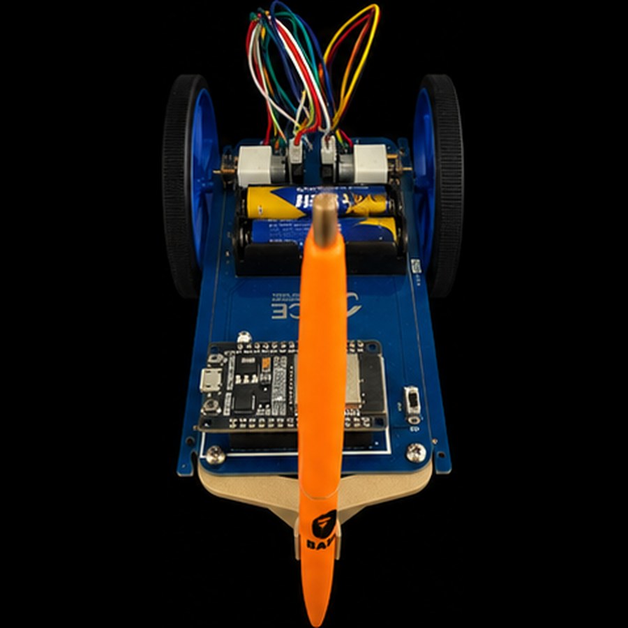
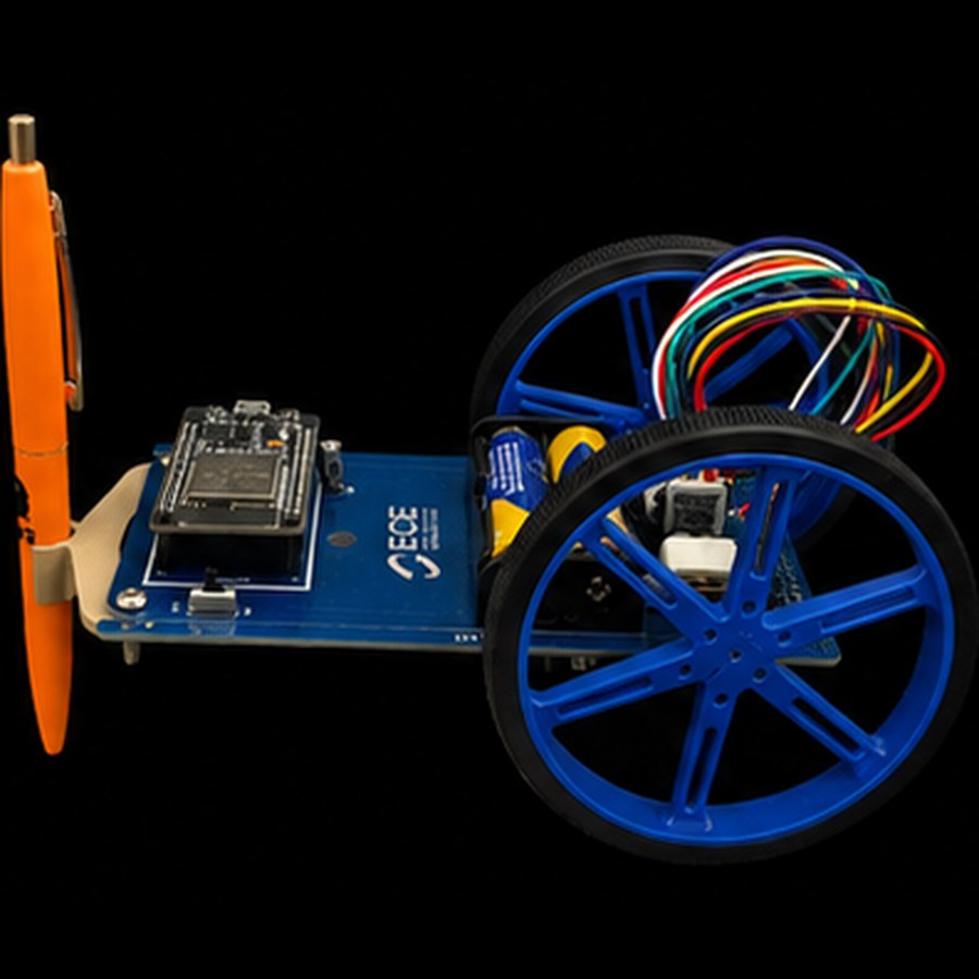
The assembled DrawBot: Gyrobot PCB, ESP32 and its pen

The closed loop,
explained simply.

Never trust, always measure.

Ask a motor to go forward 20 cm and it will do roughly that, roughly being the problem. The robot keeps comparing what it was asked (the setpoint) with what its sensors say it did (the measurement). The difference is the error; a PID corrector turns it into a new motor command, dozens of times per second:

Required vs
achieved.

Measured, not estimated.

TestRequiredAchieved
Straight lines ±1 cm over 20–40 cm Stable & within tolerance OK
90° rotations ±5° Last angle slightly obtuse Partial
Circle radius 2–20 cm, ±5 mm Clean & closed from 13 cm Partial
Circle closure ≤ 5 mm gap 6–15 mm depending on radius Close
North alignment ±10° from any start Verified by compass OK

What the robot
taught us.

A full V-cycle, one robot for three.

Hardware

  • Move or shield the magnetometer away from the motors' electromagnetic fields.
  • Grippier tyres to kill the wheel slip that ruined tight rotations.
  • A small servo to lift and drop the pen: complex figures without parasite lines.

Software

  • Fuse magnetometer and IMU gyroscope (complementary or Kalman filter) for a heading immune to magnetic noise.
  • Add anti-windup to the PID so the integral term can return safely.
  • Simulate first (Python/MATLAB), version everything with Git from day one.
← Back to projects